Bienvenido! - Willkommen! - Welcome!

Bitácora Técnica de Tux&Cía., Santa Cruz de la Sierra, BO
Bitácora Central: Tux&Cía.
Bitácora de Información Avanzada: Tux&Cía.-Información
May the source be with you!

Friday, July 31, 2009

RAID 1

Source

A RAID 1 creates an exact copy (or mirror) of a set of data on two or more disks. This is useful when read performance or reliability are more important than data storage capacity. Such an array can only be as big as the smallest member disk. A classic RAID 1 mirrored pair contains two disks (see diagram), which increases reliability geometrically over a single disk. Since each member contains a complete copy of the data, and can be addressed independently, ordinary wear-and-tear reliability is raised by the power of the number of self-contained copies.
RAID 1 failure rate
As a trivial example, consider a RAID 1 with two identical models of a disk drive with a 5% probability that the disk would fail within three years. Provided that the failures are statistically independent, then the probability of both disks failing during the three year lifetime is
P(\mathrm{bothfail}) = \left(0.05\right)^2 = 0.0025 = 0.25\,\%.

Thus, the probability of losing all data is 0.25% if the first failed disk is never replaced. If only one of the disks fails, no data would be lost, assuming the failed disk is replaced before the second disk fails.

However, since two identical disks are used and since their usage patterns are also identical, their failures can not be assumed to be independent. Thus, the probability of losing all data, if the first failed disk is not replaced, is considerably higher than 0.25% but still below 5%.


RAID 0 failure rate
Reliability of a given RAID 0 set is equal to the average reliability of each disk divided by the number of disks in the set:
\mathrm{MTTF}_{\mathrm{group}} \approx \frac{\mathrm{MTTF}_{\mathrm{disk}}}{\mathrm{number}}

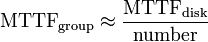
That is, reliability (as measured by mean time to failure (MTTF) or mean time between failures (MTBF) is roughly inversely proportional to the number of members – so a set of two disks is roughly half as reliable as a single disk. If there were a probability of 5% that the disk would fail within three years, in a two disk array, that probability would be upped to \mathbb{P}(\mbox{at least one fails}) = 1 - \mathbb{P}(\mbox{neither fails}) = 1 - (1 - 0.05)^2 = 0.0975 = 9.75\,\%.

The reason for this is that the file system is distributed across all disks. When a drive fails the file system cannot cope with such a large loss of data and coherency since the data is "striped" across all drives (the data cannot be recovered without the missing disk). Data can be recovered using special tools, however, this data will be incomplete and most likely corrupt, and recovery of drive data is very costly and not guaranteed.


RAID 1 performance
Since all the data exists in two or more copies, each with its own hardware, the read performance can go up roughly as a linear multiple of the number of copies. That is, a RAID 1 array of two drives can be reading in two different places at the same time, though not all implementations of RAID 1 do this.[5] To maximize performance benefits of RAID 1, independent disk controllers are recommended, one for each disk. Some refer to this practice as splitting or duplexing. When reading, both disks can be accessed independently and requested sectors can be split evenly between the disks. For the usual mirror of two disks, this would, in theory, double the transfer rate when reading. The apparent access time of the array would be half that of a single drive. Unlike RAID 0, this would be for all access patterns, as all the data are present on all the disks. In reality, the need to move the drive heads to the next block (to skip blocks already read by the other drives) can effectively mitigate speed advantages for sequential access. Read performance can be further improved by adding drives to the mirror. Many older IDE RAID 1 controllers read only from one disk in the pair, so their read performance is always that of a single disk. Some older RAID 1 implementations would also read both disks simultaneously and compare the data to detect errors. The error detection and correction on modern disks makes this less useful in environments requiring normal availability. When writing, the array performs like a single disk, as all mirrors must be written with the data. Note that these performance scenarios are in the best case with optimal access patterns.
RAID 1 has many administrative advantages. For instance, in some environments, it is possible to "split the mirror": declare one disk as inactive, do a backup of that disk, and then "rebuild" the mirror. This is useful in situations where the file system must be constantly available. This requires that the application supports recovery from the image of data on the disk at the point of the mirror split. This procedure is less critical in the presence of the "snapshot" feature of some file systems, in which some space is reserved for changes, presenting a static point-in-time view of the file system. Alternatively, a new disk can be substituted so that the inactive disk can be kept in much the same way as traditional backup. To keep redundancy during the backup process, some controllers support adding a third disk to an active pair. After a rebuild to the third disk completes, it is made inactive and backed up as described above.

RAID 5

Source
Diagram of a RAID 5 setup with distributed parity with each color representing the group of blocks in the respective parity block (a stripe). This diagram shows left asymmetric algorithm

A RAID 5 uses block-level striping with parity data distributed across all member disks. RAID 5 has achieved popularity due to its low cost of redundancy. This can be seen by comparing the number of drives needed to achieve a given capacity. RAID 1 or RAID 0+1, which yield redundancy, give only s / 2 storage capacity, where s is the sum of the capacities of n drives used. In RAID 5, the yield is s \times (n - 1)/n. As an example, four 1TB drives can be made into a 2 TB redundant array under RAID 1 or RAID 1+0, but the same four drives can be used to build a 3 TB array under RAID 5. Although RAID 5 is commonly implemented in a disk controller, some with hardware support for parity calculations (hardware RAID cards) and some using the main system processor (motherboard based RAID controllers), it can also be done at the operating system level, e.g., using Windows Dynamic Disks or with
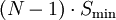
 mdadm in Linux. A minimum of three disks is required for a complete RAID 5 configuration. In some implementations a degraded RAID 5 disk set can be made (three disk set of which only two are online), while mdadm supports a fully-functional (non-degraded) RAID 5 setup with two disks - which function as a slow RAID-1, but can be expanded with further volumes.
In the example, a read request for block A1 would be serviced by disk 0. A simultaneous read request for block B1 would have to wait, but a read request for B2 could be serviced concurrently by disk 1.
RAID 5 parity handling

A concurrent series of blocks (one on each of the disks in an array) is collectively called a stripe. If another block, or some portion thereof, is written on that same stripe, the parity block, or some portion thereof, is recalculated and rewritten. For small writes, this requires...

  • Read the old data block
  • Read the old parity block
  • Compare the old data block with the write request. For each bit that has flipped (changed from 0 to 1, or from 1 to 0) in the data block, flip the corresponding bit in the parity block
  • Write the new data block
  • Write the new parity block

The disk used for the parity block is staggered from one stripe to the next, hence the term distributed parity blocks. RAID 5 writes are expensive in terms of disk operations and traffic between the disks and the controller.
The parity blocks are not read on data reads, since this would be unnecessary overhead and would diminish performance. The parity blocks are read, however, when a read of blocks in the stripe and within the parity block in the stripe are used to reconstruct the errant sector. The CRC error is thus hidden from the main computer. Likewise, should a disk fail in the array, the parity blocks from the surviving disks are combined mathematically with the data blocks from the surviving disks to reconstruct the data on the failed drive on-the-fly.
This is sometimes called Interim Data Recovery Mode. The computer knows that a disk drive has failed, but this is only so that the operating system can notify the administrator that a drive needs replacement; applications running on the computer are unaware of the failure. Reading and writing to the drive array continues seamlessly, though with some performance degradation.
RAID 5 disk failure rate

The maximum number of drives in a RAID 5 redundancy group is theoretically unlimited, but it is common practice to limit the number of drives. The tradeoffs of larger redundancy groups are greater probability of a simultaneous double disk failure, the increased time to rebuild a redundancy group, and the greater probability of encountering an unrecoverable sector during RAID reconstruction.
As the number of disks in a RAID 5 group increases, the mean time between failures (MTBF, the reciprocal of the failure rate) can become lower than that of a single disk.
This happens when the likelihood of a second disk's failing out of N − 1 dependent disks, within the time it takes to detect, replace and recreate a first failed disk, becomes larger than the likelihood of a single disk's failing.
Worsening this issue has been a relatively stagnant unrecoverable read-error rate of disks for the last few years, which is typically on the order of one error in 1014 bits for SATA drives.[6] As disk densities have gone up drastically (> 1 TB) in recent years, it actually becomes probable with a ~10 TB array that an unrecoverable read error will occur during a RAID-5 rebuild.[6] Some of these potential errors can be avoided in RAID systems that automatically and periodically test their disks at times of low demand.[7] Expensive enterprise-class disks with lower densities and better error rates of about 1 in 1015 bits can improve the odds slightly as well. But the general problem remains that, for modern drives with moving parts that use most of their capacity regularly, the disk capacity is now in the same order of magnitude as the (inverted) failure rate, unlike decades earlier when they were a safer two or more magnitudes apart. Furthermore, RAID rebuilding pushes a disk system to its maximum throughput, virtually guaranteeing a failure in the short time it runs. Even enterprise-class RAID 5 setups will suffer unrecoverable errors in coming years, unless manufacturers are able to establish a new level of mass-storage reliability through lower failure rates or improved error recovery.
Nevertheless, there are some short-term strategies for reducing the possibility of failures during recovery.
RAID 6
provides dual-parity protection, allowing the RAID system to maintain single-failure tolerance until the failed disk has been replaced and the second parity stripe rebuilt. Some RAID implementations include a hot-spare disk to speed up replacement. Also, drive failures do not occur randomly, but follow the "bathtub curve". Most failures occur early and late in the life of the device, and are often connected to production in a way that skews the failures toward specific manufacturing lots. RAID vendors can try to avoid these lot-based problems by ensuring that all the disks in a redundancy group are from different lots.
Solid-state drives (SSDs) may present a revolutionary instead of evolutionary way of dealing with increasing RAID-5 rebuild limitations. With encouragement from many flash-SSD manufacturers, JEDEC is preparing to set standards in 2009 for measuring UBER (uncorrectable bit error rates) and "raw" bit error rates (error rates before ECC, error correction code).[8] But even the economy-class Intel X25-M SSD claims an unrecoverable error rate of 1 sector in 1015 bits and an MTBF of two million hours.[9] Ironically, the much-faster throughput of SSDs (STEC claims its enterprise-class Zeus SSDs exceed 200 times the transactional performance of today's 15k-RPM, enterprise-class HDDs)[10] suggests that a similar error rate (1 in 1015) will result a two-magnitude shortening of MTBF.
RAID 5 performance
RAID 5 implementations suffer from poor performance when faced with a workload which includes many writes which are smaller than the capacity of a single stripe.[citation needed] This is because parity must be updated on each write, requiring read-modify-write sequences for both the data block and the parity block. More complex implementations may include a non-volatile write back cache to reduce the performance impact of incremental parity updates.
Random write performance is poor, especially at high concurrency levels common in large multi-user databases. The read-modify-write cycle requirement of RAID 5's parity implementation penalizes random writes by as much as an order of magnitude compared to RAID 0.[11]
Performance problems can be so severe that some database experts have formed a group called BAARF — the Battle Against Any Raid Five.[12]
The read performance of RAID 5 is almost as good as RAID 0 for the same number of disks. Except for the parity blocks, the distribution of data over the drives follows the same pattern as RAID 0. The reason RAID 5 is slightly slower is that the disks must skip over the parity blocks.
In the event of a system failure while there are active writes, the parity of a stripe may become inconsistent with the data. If this is not detected and repaired before a disk or block fails, data loss may ensue as incorrect parity will be used to reconstruct the missing block in that stripe. This potential vulnerability is sometimes known as the write hole. Battery-backed cache and similar techniques are commonly used to reduce the window of opportunity for this to occur. The same issue occurs for RAID-6.
RAID 5 usable sizeParity data uses up the capacity of one drive in the array (this can be seen by comparing it with RAID 4: RAID 5 distributes the parity data across the disks, while RAID 4 centralizes it on one disk, but the amount of parity data is the same). If the drives vary in capacity, the smallest of them sets the limit. Therefore, the usable capacity of a RAID 5 array is (N-1) \cdot S_{\mathrm{min}}, where N is the total number of drives in the array and Smin is the capacity of the smallest drive in the array.
The number of hard disks that can belong to a single array is theoretically unlimited.
ZFS RAID 5
ZFS
raid is based on the ideas behind RAID 5. It is similar to RAID-5 but uses variable stripe width to eliminate the RAID-5 write hole (stripe corruption due to loss of power between data and parity updates).[13]

Concatenation (SPAN)

Source
Diagram of a JBOD setup.

The controller treats each drive as a stand-alone disk, therefore each drive is an independent logical drive. Concatenation does not provide data redundancy.
Concatenation or spanning of disks is not one of the numbered RAID levels, but it is a popular method for combining multiple physical disk drives into a single virtual disk. It provides no data redundancy. As the name implies, disks are merely concatenated together, end to beginning, so they appear to be a single large disk.
Concatenation may be thought of as the inverse of partitioning. Whereas partitioning takes one physical drive and creates two or more logical drives, concatenation uses two or more physical drives to create one logical drive.
In that it consists of an array of independent disks, it can be thought of as a distant relative of RAID. Concatenation is sometimes used to turn several odd-sized drives into one larger useful drive, which cannot be done with RAID 0. For example, JBOD ("just a bunch of disks") could combine 3 GB, 15 GB, 5.5 GB, and 12 GB drives into a logical drive at 35.5 GB, which is often more useful than the individual drives separately.
In the diagram to the right, data are concatenated from the end of disk 0 (block A63) to the beginning of disk 1 (block A64); end of disk 1 (block A91) to the beginning of disk 2 (block A92). If RAID 0 were used, then disk 0 and disk 2 would be truncated to 28 blocks, the size of the smallest disk in the array (disk 1) for a total size of 84 blocks.
Some RAID controllers use JBOD to refer to configuring drives without RAID features. Each drive shows up separately in the OS. This JBOD is not the same as concatenation.
Many Linux distributions use the terms "linear mode" or "append mode". The Mac OS X 10.4 implementation – called a "Concatenated Disk Set" – does not leave the user with any usable data on the remaining drives if one drive fails in a concatenated disk set, although the disks otherwise operate as described above.
Concatenation is one of the uses of the Logical Volume Manager in Linux, which can be used to create virtual drives spanning multiple physical drives and/or partitions.
Microsoft's Windows Home Server employs drive extender technology, whereby an array of independent disks (JBOD) are combined by the OS to form a single pool of available storage. This storage is presented to the user as a single set of network shares. Drive extender technology expands on the normal features of concatenation by providing data redundancy through software – a shared folder can be marked for duplication, which signals to the OS that a copy of the data should be kept on multiple physical disks, whilst the user will only ever see a single instance of their data.[1]
The ZFS combined filesystem and RAID software does not support this mode for pool configuration, when disks are added to a storage pool (even if they are of differning sizes) they are always in a (dynamic) stripe. When used in the context of ZFS the term JBOD refers to seeing the drives/luns without a hardware (or other software) RAID.

GPS maps VE

Source
IngeoMaps.com
Un servicio gratuito que te permite buscar direcciones de todos los rincones de Venezuela.

VirtualBox Guest Additions

Download
Source: Virtuatopia
VirtualBox Guest Additions are a package of programs and drivers which are installed onto guest operating systems running in virtual machines to improve the guest's performance and usability.
In this chapter of VirtualBox 2 Essentials we will look at the VirtualBox Guest Additions features, installation, platform support and management.
VirtualBox Guest Additions Features
When installed on a guest operating system, VirtualBox Guest Additions provide the following enhancements:
  • Host/Guest Time Synchronization - Ensures that the system times of the guest and host are synchronized at regular intervals thereby preventing the virtualization time drift often encountered with guest operating systems running in virtual machines.
  • Seamless Window Support - One of the most compelling features of VirtualBox, seamless windows allow the window of an application running on the desktop of a guest operating system to be placed on the desktop of the host operating system such that it appears to be running directly on the host rather than within a virtual machine.
  • Shared Folders - Provides the ability to make folders/directories on the host file system available to guest operating systems running inside VirtualBox virtual machines. This topic is covered in more detail in the VirtualBox Shared Folders chapter.
  • Shared Clipboard - Allows the guest and host operating systems to access each others cut and paste clipboards enabling easy transfer of text and objects between the two environments. Control over clipboard access is controlled via the VirtualBox preferences settings, details of which can be found in the Configuring the VirtualBox Environment chapter.
  • Automated Windows Logon - Guest additions allow Windows login credentials to be stored in a master repository and used to automatically log into one or more Windows guests.
  • Mouse Pointer Enhancements - Without the guest additions installed, clicking in a virtual machine window captures the mouse focus and locks it into the window until the host key (the right hand Ctrl key by default) is pressed. With guest additions installed, it is no longer necessary to click in the virtual machine window to establish focus and press the host key to release focus. Instead, the focus will switch automatically between the guest and host as the pointer travels in and out of the virtual machine window.
  • Improved Video Support - The guest additions provide improved video performance and a greater range of video modes and resolutions. In the case of Linux guests, the additions also cause the desktop environment of the guest to resize and change resolution when the virtual machine window is resized.
Support Guest Operating Systems
The VirtualBox Guest Additions are currently supported on the following guest operating systems:
Windows Vista, Windows XP, Windows Server 2003, Windows 2000, Windows NT 4.0
Fedora Core 4, 5, 6, 7, 8
Red Hat Enterprise Linux 3, 4, 5
SUSE Linux 9, 10.1, 10.2, 10.3
openSUSE 9, 10.1, 10.2, 10.3
Ubuntu 5.10, 6.06, 7.04, 7.10, 8.04, 8.10
Note that the list of supported guests is constantly evolving such that an operating system not listed above may still be able to run the VirtualBox Guest Additions. As a general rule, it won't do any harm to try the guest additions even if the guest is not listed as being supported.
The VirtualBox Guest Additions ISO File
The VirtualBox Guest Additions are contained in an ISO image file which is installed on the host system along with the rest of the VirtualBox environment. The location of image file, which is named VBoxGuestAdditions.iso, depends on the host operating system type.
  • On Windows based hosts, the file is located in C\Program Files\Sun\xVM VirtualBox.
  • On Linux hosts the file will, by default, be located in /opt/VirtualBox-/additions where represents the installed version of VirtualBox. If an alternate location for VirtualBox was specified during the installation location, then the path will need to be adjusted accordingly.
  • On Solaris hosts, assuming the default installation location was selected, the guest additions ISO image will be found in /opt/VirtualBox/additions.
  • On Mac OS X hosts, the ISO image file is located in the VirtualBox application bundle. To locate the the file, start the Finder, right click on the VirtualBox icon and select Show Package Contents).

The ISO image contains executable files intended to autorun when the image is mounted as a virtual CD/DVD device on a virtual machine. The correct executable depends on the guest operating system and virtual machine architecture (i.e 32-bit or 64-bit) as outlined below:

  • VBoxLinuxAdditions-x86.run - A shell script for installing VirtualBox Guest additions on 32-bit Linux guests.
  • VBoxLinuxAdditions-amd64.run - A shell script for installing VirtualBox Guest additions on 64-bit Linux guests.
  • VBoxWindowsAdditions.exe - The main Windows VirtualBox Guest Additions installation executable. When run this program decides whether to install the 32-bit or 64-bit guest additions using one of the following executables.
  • VBoxWindowsAdditions-x86.exe - The 32-bit VirtualBox Guest Additions executable for Windows guest systems. The is executed automatically by the main VBoxWindowsAdditions.exe installed on 32-bit guest.
  • VBoxWindowsAdditions-amd64.exe - The 64-bit VirtualBox Guest Additions executable for Windows guest systems. The is executed automatically by the main VBoxWindowsAdditions.exe installed on 64-bit guests.

Whilst the ISO image file may be manually added to the VirtualBox virtual media library and mounted on a virtual machine as a virtual CD/DVD device, a quicker mechanism is provided via the Devices... menu of the virtual machine window.
Installing VirtualBox Guest Additions on Windows
As previously discussed, the VirtualBox Guest Additions reside in an ISO image file which is bundled with the VirtualBox software. This image file must be mounted as a virtual CD-ROM on the virtual machine on which the additions are to be installed. VirtualBox provides a shortcut to performing this task in the form of the Devices->Install Guest Additions.... menu option. When selected, this option mounts the VBoxGuestAdditions.iso as a virtual CD-ROM and, assuming that AutoPlay is enabled on the guest Windows operating system, the VirtualBox Guest Additions installer will automatically start. If AutoPlay is not enabled, navigate to the CD-ROM using Windows Explorer and double click on VBoxWindowsAdditions.exe to initiate the installation process. Once invoked, the Sun xVM VirtualBox Guest Additions Setup Welcome screen will appear. Click Next > to proceed to the license screen, review the license and click I Agree to display the installation screen as illustrated below:
Image:Virtualbox guest additions install.jpg
Either accept the default installation folder or browse to the desired location before clicking the Install button to initiate the installation process. The progress of the installation is communicate via a progress bar and a scrolling report of the various tasks as they are performed:
Image:Virtualbox guest additions installation progress.jpg
Once the installation is complete, the guest operating system must be rebooted for the guest additions to take effect. The reboot may be initiated from the Setup screen, or performed manually at a later, more convenient time.
Manually Extracting the VirtualBox Windows Driver
The VirtualBox Guest Additions installer automatically extracts and installs the VirtualBox device drivers. In some situations, it is possible that just the drivers, and none of the other guest addition features may be required. In this situation, perform the following steps to extract the device drivers:

  1. Mount the VirtualBox Guest Additions CD-ROM following steps outlined previously
  2. Open a command prompt window and change directory to the location of the guest additions virtual CD-ROM
  3. Execute one of the following commands depending on the guest operating system architecture:
    VBoxWindowsAdditions-x86.exe /extract /D=C:\VBoxDrivers
    VBoxWindowsAdditions-amd64.exe /extract /D=C:\VBoxDrivers

Note that the above commands extract the driver files into C:\VBoxDrivers\x86 and C:\VBoxDrivers\amd64 respectively. Alternate locations may be specified by modifying the /D directive accordingly.

Vinum volume manager

Vinum, is a logical volume manager, also called Software RAID, allowing implementations of the RAID-0, RAID-1 and RAID-5 models, both individually and in combination
Vinum is part of the base distribution of the FreeBSD operating system. Versions exist for NetBSD, OpenBSD and DragonFly BSD. Vinum source code is currently maintained in the FreeBSD and NetBSD source trees. Vinum supports raid levels 0, 1, 5, and JBOD.
Note:
vinum is invoked as gvinum on FreeBSD version 5.4 and up.
Software RAID vs. Hardware RAID
The distribution of data across multiple disks can be managed by either dedicated hardware or by software. Additionally, there are hybrid RAIDs that are partly software- and partly hardware-based solutions.
With a software implementation, the operating system manages the disks of the array through the normal drive controller (ATA, SATA, SCSI, Fibre Channel, etc.). With present CPU speeds, software RAID can be faster than hardware RAID.
A hardware implementation of RAID requires at a minimum a special-purpose RAID controller. On a desktop system, this may be a PCI expansion card, or might be a capability built in to the motherboard. In larger RAIDs, the controller and disks are usually housed in an external multi-bay enclosure. This controller handles the management of the disks, and performs parity calculations (needed for many RAID levels). This option tends to provide better performance, and makes operating system support easier.
Hardware implementations also typically support hot swapping, allowing failed drives to be replaced while the system is running. In rare cases hardware controllers have become faulty, which can result in data loss. Hybrid RAIDs have become very popular with the introduction of inexpensive hardware RAID controllers. The hardware is a normal disk controller that has no RAID features, but there is a boot-time application that allows users to set up RAIDs that are controlled via the BIOS. When any modern operating system is used, it will need specialized RAID drivers that will make the array look like a single block device.
Since these controllers actually do all calculations in software, not hardware, they are often called "fakeraids". Unlike software RAID, these "fakeraids" typically cannot span multiple controllers.
Example configuration
A simple example to mirror drive enterprise to drive excelsior (RAID1)

drive enterprise device /dev/da1s1d
drive excelsior device /dev/da2s1d
volume mirror
plex org concat
sd length 512m drive enterprise
plex org concat
sd length 512m drive excelsior

Software RAID

Operating system based ("software RAID")
Software implementations are now provided by many operating systems. A software layer sits above the (generally block-based) disk device drivers and provides an abstraction layer between the logical drives (RAIDs) and physical drives. Most common levels are
RAID 0 (striping across multiple drives for increased space and performance)
RAID 1 (mirroring two drives), followed by RAID 1+0, RAID 0+1
RAID 5 (data striping with parity) are supported.
  • FreeBSD supports RAID 0, RAID 1, RAID 3, and RAID 5 and all layerings of the above via GEOM modules[8][9] and ccd.[10], as well as supporting RAID 0, RAID 1, RAID-Z, and RAID-Z2 (similar to RAID-5 and RAID-6 respectively), plus nested combinations of those via ZFS.
  • Linux supports RAID 0, RAID 1, RAID 4, RAID 5, RAID 6 and all layerings of the above.[11][12]
  • Microsoft's server operating systems support 3 RAID levels; RAID 0, RAID 1, and RAID 5. Some of the Microsoft desktop operating systems support RAID such as Windows XP Professional which supports RAID level 0 in addition to spanning multiple disks but only if using dynamic disks and volumes. Windows XP supports RAID 0, 1, and 5 with a simple file patch [13]. RAID functionality in Windows is slower than hardware RAID, but allows a RAID array to be moved to another machine with no compatibility issues.
  • NetBSD supports RAID 0, RAID 1, RAID 4 and RAID 5 (and any nested combination of those like 1+0) via its software implementation, named RAIDframe.
  • OpenBSD aims to support RAID 0, RAID 1, RAID 4 and RAID 5 via its software implementation softraid.
  • OpenSolaris and Solaris 10 supports RAID 0, RAID 1, RAID 5 (or the similar "RAID Z" found only on ZFS), and RAID 6 (and any nested combination of those like 1+0) via ZFS and now has the ability to boot from a ZFS volume on both x86 and UltraSPARC. Through SVM, Solaris 10 and earlier versions support RAID 0, RAID 1, and RAID 5 on both system and data drives.

Software RAID has advantages and disadvantages compared to hardware RAID. The software must run on a host server attached to storage, and server's processor must dedicate processing time to run the RAID software. This is negligible for RAID 0 and RAID 1, but may become significant when using parity-based arrays and either accessing several arrays at the same time or running many disks. Furthermore all the busses between the processor and the disk controller must carry the extra data required by RAID which may cause congestion.
Another concern with operating system-based RAID is the boot process. It can be difficult or impossible to set up the boot process such that it can fail over to another drive if the usual boot drive fails. Such systems can require manual intervention to make the machine bootable again after a failure. There are exceptions to this, such as the LILO bootloader for Linux, loader for FreeBSD[14] , and some configurations of the GRUB bootloader natively understand RAID-1 and can load a kernel. If the BIOS recognizes a broken first disk and refers bootstrapping to the next disk, such a system will come up without intervention, but the BIOS might or might not do that as intended. A hardware RAID controller typically has explicit programming to decide that a disk is broken and fall through to the next disk.
Hardware RAID controllers can also carry battery-powered cache memory. For data safety in modern systems the user of software RAID might need to turn the write-back cache on the disk off (but some drives have their own battery/capacitors on the write-back cache, a UPS, and/or implement atomicity in various ways, etc). Turning off the write cache has a performance penalty that can, depending on workload and how well supported command queuing in the disk system is, be significant. The battery backed cache on a RAID controller is one solution to have a safe write-back cache.
Finally operating system-based RAID usually uses formats specific to the operating system in question so it cannot generally be used for partitions that are shared between operating systems as part of a multi-boot setup. However, this allows RAID disks to be moved from one computer to a computer with an operating system or file system of the same type, which can be more difficult when using hardware RAID (e.g. #1: When one computer uses a hardware RAID controller from one manufacturer and another computer uses a controller from a different manufacturer, drives typically cannot be interchanged. e.g. #2: If the hardware controller 'dies' before the disks do, data may become unrecoverable unless a hardware controller of the same type is obtained, unlike with firmware-based or software-based RAID).
Most operating system-based implementations allow RAIDs to be created from partitions rather than entire physical drives. For instance, an administrator could divide an odd number of disks into two partitions per disk, mirror partitions across disks and stripe a volume across the mirrored partitions to emulate IBM's RAID 1E configuration. Using partitions in this way also allows mixing reliability levels on the same set of disks. For example, one could have a very robust RAID 1 partition for important files, and a less robust RAID 5 or RAID 0 partition for less important data. (Some BIOS-based controllers offer similar features, e.g. Intel Matrix RAID.) Using two partitions on the same drive in the same RAID is, however, dangerous.
e.g. #1: Having all partitions of a RAID-1 on the same drive will, obviously, make all the data inaccessible if the single drive fails.
e.g. #2: In a RAID 5 array composed of four drives 250 + 250 + 250 + 500 GB, with the 500-GB drive split into two 250 GB partitions, a failure of this drive will remove two partitions from the array, causing all of the data held on it to be lost.

RAID

RAID is an acronym first defined at the University of California, Berkeley in 1987 to describe a redundant array of inexpensive disks,[1] a technology that allowed computer users to achieve high levels of storage reliability from low-cost and less reliable PC-class disk-drive components, via the technique of arranging the devices into arrays for redundancy.
Redundancy is achieved by either writing the same data to multiple drives (known as mirroring), or writing extra data (known as parity data) across the array, calculated such that the failure of one (or possibly more, depending on the type of RAID) disks in the array will not result in loss of data. A failed disk may be replaced by a new one, and the lost data reconstructed from the remaining data and the parity data. Organizing disks into a redundant array decreases the usable storage capacity. For instance, a 2-disk RAID 1 array loses half of the total capacity that would have otherwise been available using both disks independently, and a RAID 5 array with several disks loses the capacity of one disk. Other types of RAID arrays are arranged so that they are faster to write to and read from than a single disk.

There are various combinations of these approaches giving different trade-offs of protection against data loss, capacity, and speed. RAID levels 0, 1, and 5 are the most commonly found, and cover most requirements.

  • RAID 0 (striped disks) distributes data across several disks in a way that gives improved speed at any given instant. If one disk fails, however, all of the data on the array will be lost, as there is neither parity nor mirroring.
  • RAID 1 mirrors the contents of the disks, making a form of 1:1 ratio realtime backup. The contents of each disk in the array are identical to that of every other disk in the array.
  • RAID 5 (striped disks with parity) combines three or more disks in a way that protects data against loss of any one disk. The storage capacity of the array is reduced by one disk.
  • RAID 6 (striped disks with dual parity) can recover from the loss of two disks.
  • RAID 10 (or 1+0) uses both striping and mirroring. "01" or "0+1" is sometimes distinguished from "10" or "1+0": a striped set of mirrored subsets and a mirrored set of striped subsets are both valid, but distinct, configurations.

RAID can involve significant computation when reading and writing information. With traditional "real" RAID hardware, a separate controller does this computation. In other cases the operating system or simpler and less expensive controllers require the host computer's processor to do the computing, which reduces the computer's performance on processor-intensive tasks (see "Software RAID" and "Fake RAID" below). Simpler RAID controllers may provide only levels 0 and 1, which require less processing.
RAID systems with redundancy continue working without interruption when one (or possibly more, depending on the type of RAID) disks of the array fail, although they are then vulnerable to further failures. When the bad disk is replaced by a new one the array is rebuilt while the system continues to operate normally. Some systems have to be powered down when removing or adding a drive; others support hot swapping, allowing drives to be replaced without powering down. RAID with hot-swapping is often used in high availability systems, where it is important that the system remains running as much of the time as possible.

RAID is not a good alternative to backing up data. Data may become damaged or destroyed without harm to the drive(s) on which they are stored. For example, some of the data may be overwritten by a system malfunction; a file may be damaged or deleted by user error or malice and not noticed for days or weeks; and, of course, the entire array is at risk of physical damage.
Principles
RAID combines two or more physical hard disks into a single logical unit by using either special hardware or software. Hardware solutions often are designed to present themselves to the attached system as a single hard drive, so that the operating system would be unaware of the technical workings. For example, you might configure a 1TB RAID 5 array using three 500GB hard drives in hardware RAID, the operating system would simply be presented with a "single" 1TB volume. Software solutions are typically implemented in the operating system and would present the RAID drive as a single volume to applications running upon the operating system.
There are three key concepts in RAID:
mirroring
, the copying of data to more than one disk;
striping, the splitting of data across more than one disk; and
error correction, where redundant data is stored to allow problems to be detected and possibly fixed (known as fault tolerance).
Different RAID levels use one or more of these techniques, depending on the system requirements. RAID's main aim can be either to improve reliability and availability of data, ensuring that important data is available more often than not (e.g. a database of customer orders), or merely to improve the access speed to files (e.g. for a system that delivers video on demand TV programs to many viewers).
Standard levels
RAID0
"Striped set without parity" or "Striping". Provides improved performance and additional storage but no redundancy or fault tolerance. Any disk failure destroys the array, which has greater consequences with more disks in the array (at a minimum, catastrophic data loss is twice as severe compared to single drives without RAID). A single disk failure destroys the entire array because when data is written to a RAID 0 drive, the data is broken into fragments. The number of fragments is dictated by the number of disks in the array. The fragments are written to their respective disks simultaneously on the same sector. This allows smaller sections of the entire chunk of data to be read off the drive in parallel, increasing bandwidth. RAID 0 does not implement error checking so any error is unrecoverable. More disks in the array means higher bandwidth, but greater risk of data loss.
RAID1
'Mirrored set without parity' or 'Mirroring'. Provides fault tolerance from disk errors and failure of all but one of the drives. Increased read performance occurs when using a multi-threaded operating system that supports split seeks, as well as a very small performance reduction when writing. Array continues to operate so long as at least one drive is functioning. Using RAID 1 with a separate controller for each disk is sometimes called duplexing.
RAID5
Striped set with distributed parity or interleave parity. Distributed parity requires all drives but one to be present to operate; drive failure requires replacement, but the array is not destroyed by a single drive failure. Upon drive failure, any subsequent reads can be calculated from the distributed parity such that the drive failure is masked from the end user. The array will have data loss in the event of a second drive failure and is vulnerable until the data that was on the failed drive is rebuilt onto a replacement drive. A single drive failure in the set will result in reduced performance of the entire set until the failed drive has been replaced and rebuilt.

RAID Level 0RAID Level 1RAID Level 5

Wednesday, July 29, 2009

Nvidia-Geforce tuning

Source
Echtes 3D aktivieren, zweite Grafikkarte zuschalten, scharfe Videos ohne Flimmern – mit der Nvidia Systemsteuerung holen Sie alles aus Ihrer Geforce Grafikkarte raus.

IBM DeathStars

Source
Ultrastar

IBM (later Hitachi) is widely known in data recovery business for their line of DeskStar HDDs also known as DeathStars. These hard drives, mostly DTLA and AVER families, became infamous for their reportedly high failure rates. It is believed their problems were mainly connected with glass platters - new technology introduced by IBM in these hard drives. After some time magnetic layer started to fall off the platters creating dust inside the HDA(Head Disk Assembly) that led to massive head crashes and large number of bad sectors making the data inaccessible.
Apart from this IBM used soldering alloy of poor quality and had deficient PCB layout that caused looseness in contacts between the PCB and HDA that in turn led to firmware corruption. If you attempt to boot up from such drive or read any data from it you would get "Primary Master Hard Disk Fail" or "Operating system not found" or "USB Device malfunctioned" error or "S.M.A.R.T. Capable But Command Failed" or some other hard drive error on boot. It's critical at this point to stop any manipulations with the hard drive and send it for evaluation to our lab. Any further attempts to read these areas would shorten the drive's life and may result in further unrecoverable data loss.

IBM spins up fine. The heads click but there is no grinding noise. It does this for a bit then it spins down and the clicking stops. The drive is not recognized by the bios. When it happened the computer itself was on then something clicked (probably a short or surge) and the whole system shut down. I think something on the drive's primary control board may have fried.
Tristan B.
Abbotsford, British Columbia, Canada

Another common data loss problem for all IBM-Hitachi hard drives is burnt components on the cirquit board(PCB). Hard drives are very vulnerable to power surges and bad power supply unit combined with power streak is usually enough to burn spindle driver chip on the PCB. If this occurs the computer would reboot itself, you would normally notice acrid smoke coming from your PC and upon power on the drive would not spin up at all.
If this is the case you can try PCB swap from another IBM drive of the same model but the chances of successful data recovery are close to 0. Moreover, newer drives sometimes "lock" incompatible PCB and after that PCB won't be able to work on the original donor drive. The fact is that most modern drives have special parameters in the ROM chip on the PCB called adaptives which are unique for this particular drive and these parameters should correspond to the HDA PCB was manufactured with. In our lab we are able to read ROM and NVRAM contents even from burnt logic boards and write it to the compatible donor board. After that donor PCB becomes fully compatible with the damaged drive and often data can be recovered after that.

There is one more problem that is typical for all IBM drives: bad sectors. After some period of time magnetic media the platters are covered with starts to degrade and bad sectors appear.
Whenever the drive hits such unreadable bad sector it could start freezing, scratching, ticking and sometimes loud clicking. If you happen to hear that unmistakable repeating scratching noise from your drive this is exactly your case. This leads to further damage to the surface and causes more data loss.

As soon as you start experiencing such symptoms while reading important files stop the drive immediately and send it to a data recovery lab. Any further attempts would just add up to the problems. In our lab we use special imaging hardware tools that are capable of reading raw sector data ignoring checksum check. That's usually the only way to retrieve as much data as possible from these LBAs.

Another quite common symptom Hitachi drives have is clicking or knocking sound. The drive spins up and the head starts clicking right away. Most often this a sign of a bad head and the drive needs heads swapped from a donor, but before doing any clean room work, it is very important to perform accurate diagnostics and eliminate a chance of possible firmware corruption that sometimes can also cause clicking.

If you experience any of the symptoms described above with your IBM DRVS-09D please feel free to contact us to get upfront quote on data recovery from your failed drive.

If you hear your IBM hard drive making some other unusual noises visit our Hard Drive Sounds page for more examples.

DFT & OGT Diagnostic Tool

Source
Looking for drivers for Hitachi hard disk drives?

Looking for drivers for Microdrive Digital Media?

Install or Optimize Your Drive
Utilities for installing or optimizing Hitachi HDDs

Analyze, Monitor and Restore Your Drive
Utilities for analyzing, monitoring and restoring Hitachi HDDs

Drive Fitness Test
The Drive Fitness Test (DFT) quickly and reliably tests SCSI, IDE and SATA drives. The DFT analyze function performs read tests without overwriting customer data. (Note: other DFT restoration utilities may overwrite data.)
Downloads

Notes

  • Ultrastar 10K300, Ultrastar 15K73 and DK32XX users, do not use DFT — Use the OGT Diagnostic Tool.
  • Does not support Microdrive Digital Media products.
  • Supports all Travelstar HDDs, except 8E, 10E and C4K series.
  • Does not support Endurastar products.
  • Does not support external USB or Firewire attached drives.
  • Compatible only with x86-based processors.
  • Does not support the PC which loads Intel ICH9M chipset. HitachiGST are working to fix this situation.

Supports Leading Drives

  • SCSI.
  • Serial ATA.
  • Parallel ATA.
  • IDE.

Analyzes Drive Fitness

  • Three modes of operation.
    - High confidence level quick test
    - Full media scan
    - Exerciser
  • Performs real-time analysis of your drive to quickly determine if problem exists.
  • Identifies system problems such as cable or temperatures.
  • Automatically logs significant drive parameters to track potential impacts to the drive operations (diskette version only).

Restores Drive Fitness

  • Erase-boot-sector utility (Use option: Erase Boot Sector).
    - Note: this utility overwrites customer data to allow repair of bad sectors.
  • Low-level format utility (Use option: Erase Disk).
    - Note: this utility overwrites customer data to allow repair of bad sectors.

Includes Utilities

  • Drive information.
  • SMART operations for supported hard disk drives.

Resources


OGT Diagnostic Tool

OGT Diagnostic Tool is a failure analysis tool for Ultrastar 10K300, Ultrastar 15K73 and DK32xx disk drives. For these drives, OGT Diagnostic Tool replaces the Drive Fitness Test.

Downloads

Notes

  • Automatically performs necessary diagnostic testing and failure analysis.
  • Windows OS-compatible only.

PRTG Network Monitor

PRTG Network Monitor is the powerful network monitoring solution from Paessler AG. It ensures the availability of network components while also measuring traffic and usage. It saves costs by avoiding outages, optimizing connections, saving time and controlling service level agreements (SLAs).
Optimize Your Network and Avoid System Downtimes
Businesses increasingly rely on their networks to move data, provide communication, and enable basic operations. Performance loss or system outages can seriously impact the bottom line of your business. Continuous network and server monitoring enables you to find problems and resolve them before they become a serious threat to your business:

  • Avoid bandwidth and server performance bottlenecks
  • Deliver better quality of service to your users by being proactive
  • Reduce costs by buying bandwidth and hardware based on actual load
  • Increase profits by avoiding losses caused by undetected system failures
  • Find peace of mind: As long as you do not hear from PRTG via email, SMS, pager, etc. you know everything is running fine and you have more time to take care of other important business

Download the freeware or the free trial and setup your network monitor within minutes.

Windows7&Vista firewall control

Source
Protects your applications from undesirable network incoming and outgoing activity, controls applications internet access. Allows you to control personal information leakage via controlling application network traffic.
Manages and synchronizes port forwarding provided by external network connection (firewall/router) box with applications requirements and activity.

TCP/IP optmizers

Source

Tuesday, July 28, 2009

64 bit M$ operating systems

Source
Benefits
  • The additional computing power,
  • the additional security and
  • obviously the benefits of breaking the 4Gb memory barrier
So what could still stop you from going 64 bit?
There’s no doubt that 64 bit is better but the problems standing against people who want to upgrade include…
  • Driver support – Less of an issue for newer hardware, but some hardware vendors still don’t have 64-bit driver support for their products and, sadly, many people only find this out after they’ve installed a 64-bit OS.
  • Firewall support – There is still no free stand-alone firewall that runs on a 64-bit version of Windows. Why? Currently if you want anything other than the standard Windows firewall these companies will force you to buy their not-really-worth-the-money security suites.
  • Software support – Apple were late to come to market with a 64-bit version of iTunes and they’re not alone. There’s still a lot of software that won’t run on a 64-bit OS.
  • Run the 64-bit version of Internet Explorer (for better stability and security) and visit YouTube, or any other website running on Adobe Flash. You’ll receive a message saying that there’s STILL no 64-bit version of the Flash player.
Drivers support, software use more than 4GB of memory and multiple core CPU’s are key to 64 bit OSes (of Micro$oft) going mainstream.

Checking integrity of files

md5summer(.org)
WinMd5Sum Portable
Due to some weaknesses in the MD5 hash function, it is better to use SHA-1 checksum keys.
Announce All modern GNU/Linux systems are featuring a sha1sum tool, similar to the md5sum too, so this there should be no problem checking the checksums on these platforms.
For MS Windows no such tool is available.
To solve this problem, I wrote a simple sha1sum tool and uploaded it along with a MS Windows binary (sha1sum.exe) to the GnuPG ftp servers. The source is also available and maybe used to check the correctness or to build own binaries. It should build on all platforms.

Download the sha1sum.exe and put it in your windows system 32 directory (e.g. C:\WINDOWS\system32) directory. You can calculate the checksums key by type sha1sum *.iso on the command prompt. E. g.:
D:\LinuxISO>sha1sum *.iso
-----------------------------
SlavaSoft fsum
A fast and handy command line utility for file integrity verification. It offers a choice of 13 of the most popular hash and checksum functions for file message digest and checksum calculation.
-----------------------------
The CryptoSys PKI Toolkit (trial, 60 days) provides you with an interface to public key cryptography functions from Visual Basic, VB6, VBA, VB.NET, VB2005, C/C++ and C# programs on any Win32-compatible system (W95/98/Me/NT4/2K/XP/2003/Vista).
-----------------------------
The HashCheck Shell Extension makes it easy for you to calculate and verify checksums (including hashes) from Windows Explorer.
First, HashCheck can process and verify the checksums/hashes stored in checksum files--these are files with a .sfv, .md4, .md5 or .sha1 file extension. Just double-click on the checksum file, and HashCheck will check the actual checksums of the listed files against those specified in the checksum file.
Single setup package for both 32-bit and x64 Windows

Herramientas de seguridad de M$

Security Tools
Assess vulnerabilities and strengthen security with these tools and technologies.
Technet.Micro$oft.com
MBSA2.1

Gusano se propaga en MSN LM y Skype

Source
Un primo de Argentina me manda por MSN LM y Skype lo sgte.:
MSN live messenger
cabron, te perdiste el concierto de belanova la cagaste por no ir, mira las fotos que tome
http:/ /get451.image-facebook.info:8081/uploads/file0493/disp.php?ref= DVC-Imagen003.JPEG.scr
skype
esta bien esta foto para ir en mi perfil?
http:/ /get451.image-facebook.info:8081/uploads/file0493/disp.php?ref= DVC-Imagen003.JPEG.scr
(Lo mismo que
"I took this picture with my newest cam, does it look ok?")
Invitándome a descargar la fotografía...
Y en realidad la supuesta fotografía tiene una extensión .scr (screensaver application)
Los archivos .scr pueden ejecutar códigos tal como todo archivo ejecutables .exe y es un buen método de los creadores de malware para infectar equipos cuyos usuarios no tienen idea de esos mecanismos ni de la tecnología informática usada para fines oscuros.
Una vez descargada y ejecutada tiene el siguiente comportamiento:
  • Agrega un auto start al registro para cargar parte del programa descargado al inicio del sistema operativo
  • Borra un proceso determinado
El gusano apareció en España el 28 Feb 2009
Puede tener los siguientes nombres:
  • 76068113.DAT
  • 93731019.SCR
  • 90395982.SCR
  • ASHWBSM.EXE
  • ACCESS.EXE
  • AVGMGENT.EXE
  • AVGSCNR.EXE
  • ASHSDLP.EXE
  • ASWUPSRC.EXE

Shield for Wifi

Protecting the web for your security, privacy and anonymity!
Get behind the Shield!
100% free VPN security!
Standard antivirus software protects your computer, but not your web activities.
HSS enables access to all information online, providing freedom to access all web content freely and securely.
Secure your entire web session and ensure your privacy online; your passwords, credit card numbers, and all of your data is secured with HSS.
HSS protects your entire web surfing session; securing your connection at both your home Internet network & Public Internet networks (both wired and wireless).
HSS protects your identity by ensuring that all web transactions (shopping, filling out forms, downloads) are secured through HTTPS.
HSS also makes you private online making your identity invisible to third party websites and ISP’s. Unless you choose to sign into a certain site, you will be anonymous for your entire web session with HSS.
The application keeps your Internet connection secure, private, and anonymous.
HSS creates a virtual private network (VPN) between your laptop or iPhone and our Internet gateway.
This impenetrable tunnel prevents snoopers, hackers, ISP’s, from viewing your web browsing activities, instant messages, downloads, credit card information or anything else you send over the network.
HSS security application employs the latest VPN technology, and is easy to install and use. ...

  • Access all of your favorite content privately
  • Secure your web session with HTTPS encryption
  • Hide your IP address for your privacy online
  • Protect from snoopers at Wi-Fi hotspots, hotels, airports, corporate offices and ISP hubs.
  • Secure your data & personal information online

Malware classification proposal

Thanks to Joanna Rutkowska (Invisiblethings.org)
Type 0: Malware which doesn’t modify OS in any undocumented way nor any other process (non-intrusive)
Type I: Malware which modifies things which should never be modified (e.g. Kernel code, BIOS which has it’s HASH stored in TPM, MSR registers, etc…)
Type II: Malware which modifies things which are designed to be modified (DATA sections)
  • Type 0 is not interesting for us
  • Type I malware is/will always be easy to spot
  • Type II is/will be very hard to find
Type I malware examples
  • Hacker Defender (and all commercial variations)
  • Sony Rootkit
  • Apropos
  • Adore (although syscall tables is not part of kernel code section, it’s still a thing which should not be modified!)
  • Suckit
  • Shadow Walker – Sherri Sparks and Jamie Butler
  • Although IDT is not a code section (actually it’s inside an INIT section of ntoskrnl), it’s still something which is not designed to be modified!
  • However it *may* be possible to convert it into a Type II (which would be very scary)
Type II malware examples
  • NDIS Network backdoor in NTRootkit by Greg Hoglund (however easy to spot because adds own NDIS protocol)
  • Klog by Sherri Sparks – “polite” IRP hooking of keyboard driver, appears in DeviceTree (but you need to know where to look)
  • He4Hook (only some versions) – Raw IRP hooking on fs driver
  • prrf by palmers (Phrack 58!) – Linux procfs smart data manipulation to hide processes (possibility to extend to arbitrary files hiding by hooking VFS data structures)
  • FU by Jamie Butler
  • PHIDE2 by 90210 – very sophisticated process hider, still however easily detectable with X-VIEW...

Burning in Linux (cdrecord)

Source
Insert a blank CD into the CD burner.
Find the device file associated with your burner (/dev/... ).
$ cdrecord --devices
Sample output:
---------------------------------------------------
0 dev='/dev/scd0' rwrw-- : '_NEC' 'DVD+RW ND=1100A'
---------------------------------------------------
Burn the image to the CD.
$ cdrecord -dev=device -tao image
Example:
$ cdrecord -dev=/dev/scd0 -tao image
-----------------------------
Use cdrecord. First, type cdrecord -scanbus in order to get the identifier numbers of your device. Then, type in a console:
cdrecord dev=x,y,z -v ISOfile.iso
On Windows, you can use burning software such as Nero, or you can download ImgBurn which is free.

Monday, July 27, 2009

Image on a USB drive

Simple way to put a .iso or .img image on a USB drive (using Windows):
  1. Download the Win32DiskImager.exe program:
    https://launchpad.net/win32-image-writer/+download
  2. Unzip the file and extract the contents to a known directory
  3. Run W32DiskImager.exe (screenshot)
  4. Select the image file (.img)
  5. Select the drive letter which corresponds to the USB key
  6. Click the "Write" button to byte-copy the image to the USB drive.

Anti-rootkits Software

Antirootkit.com aims to help ordinary computer users gain an understanding of Rootkits, what they can do and steps to remove them. This site aims to provide information on all aspects of Rootkit Information, Prevention, Detection, Indentification and Removal.
A rootkit is a program that is designed to hide itself and other programs, data, and/or activity including viruses, backdoors, keyloggers and spyware on a computer system.
A Rootkit can keep itself, other files, registry keys and network connections hidden from detection and this is why they are so dangerous.
Rootkits are used to hide the existence of Spyware, Trojans, Keyloggers and other malware on computers. They are also commonly used by hackers to hide the backdoors they install on computers.
The rise in the use of Rootkits can be seen at the moment as more Spyware creators are trying to hide their installation from the evolving Spyware scanners and virus writers trying to hide their existance.
Recent stats show that over 500,000 computers are infected with the Sony Rootkit. Are you infected?

Name Publisher OS Cost/
Rating
Aries Sony
Rootkit
Remover
Lavasoft Win Free
Archon
Scanner
X-Solve Win Trial/New
AVG
AntiRootkit
Grisoft Win/V Free
Avira
Rootkit
Detection
Avira Win Free
chkrootkit Murilo &
Jessen
Linux, BSD. Free
DarkSpy CardMagic & wowocock 2K/XP/ 2003 Free/5 star
F-Secure Blacklight
Beta
F-Secure Win Free
Gmer Gmer 2K / XP/Vista Free/5 star
Helios/
Helios Lite
MIEL
e-Security
Win Free/New
Hidden
Finder
Wenpoint 2K/XP Trial
Hook
Explorer
iDefense Win Free
IceSword XFocus Win Free/5 star
OS X
Rootkit
Hunter

Christian Hornung Mac OS X 10.4 Free
Panda
Anti-
Rootkit
(Tucan)
Panda
Software
2K/XP/ 2003 Free
Process Master Backfaces 2K/XP/
2003
30 d Trial
Radix
Anti RootKit
USEC.at Win New
RootKit
Detective
McAfee
Avert Labs
Win New
RootKit
Buster
Trend
Micro
Win Beta
RootKit
Hook Analyzer
Resplen-
dence
Win Free
Rootkit
Hunter
Boelen Linux, BSD. Free
Rootkit
Profiler LX
Tobias
Klein
Linux Free/New
Rootkit
Revealer
Sysinternals Win Free/
5 Star
RootKit
Shark
Advances.com Win Trial
RootKit
Uncover
BitDefender Win Free / New
RootKit
Unhooker
UG North 2K/XP/ 2003 Free/
5 Star
SEEM AI, nunki Win Free
Sophos
Antirootkit
Sophos Win Free
SysProt
Antirootkit
Swatkat Win Free/New
System
Virginity Verifier
Joanna Rutkowska Win Free
Unhackme Greatis Win Trial
Zeppoo Zeppoo Linux Free/New
Rootkit Removal Tools Gromozon, Rustock & Haxdoor
Removal Tools
LATEST AWARDS