This section looks at IP addressing, subnet masking, Private and Special addresses. Examples are provided to illustrate the methodology when setting up an IP network addressing scheme. We also look at Wildcard masks and Directed Broadcasts.
Subnets
Subnetting Example
Another Subnetting Example

Subnets
Subnetting Example
A customer has been given an IP address of 128.100.0.0 (a Class B address) for his company. He has specified that he requires 3 separate networks with the maximum possible number of host connections on each network.
The first two octets 128.100 are fixed since these are given by NIC as the Class B address, therefore we have the last two octets to play with. Let us examine the possibilities more closely:
- The address given
Octet 1            Octet 2         Octet 3         Octet 4
10000000           01100100        00000000        00000000
128.               100.            0.              0
- We need to create a minimum of 3 different subnets but not at the expense of the number of host addresses available to us. The following process would seem to give us 4 permutations of subnets: Looking at octet 3 specifically in binary, let us just use the first 2 bits for a subnet address:
128 64 32 16 8 4 2 1
1 1 0 0 0 0 0 0
The possible combinations for the first two bits are:11 = 192 -> 128.100.192.0 10 = 128 -> 128.100.128.0 01 = 64 -> 128.100.64.0 00 = 0 -> 128.100.0.0
However all 1's and all 0's used to be not allowed for a subnet. These subnets are called the All One's Subnet and Subnet Zero. The reason for this was that older software found it difficult to distinguish between networks 128.100.0.0/16 and the all-zeros subnet 128.100.0.0/18. The same was true of the all-ones subnet. RFC 950 therefore rules out '11' and '00' as useable subnets, we are therefore left with only two subnet addresses instead of the 3 we require.
- Let us try and use an extra bit in octet 3:
128 64 32 16 8 4 2 1
1 1 1 0 0 0 0 0
The possible combinations are now:111 = 224 -> 128.100.224.0 110 = 192 -> 128.100.192.0 101 = 160 -> 128.100.160.0 011 = 96 -> 128.100.96.0 001 = 32 -> 128.100.32.0 010 = 64 -> 128.100.64.0 100 = 128 -> 128.100.128.0 000 = 0 -> 128.100.0.0
As before all 1's and all 0's are not permitted for subnets, therefore we are left with 6 possible subnets (23 - 2):-128.100.32.0 128.100.64.0 128.100.96.0 128.100.128.0 128.100.160.0 128.100.192.0
- This leaves the rest of the bits (from power 16 downwards) in octet 3 and all the bits in octet 4 to construct the individual host addresses, the permutations amount to many thousands of hosts which should be plenty. Below is an example of a host address in subnet 128.100.192.0:-
128.100.194.23
On first inspection it would appear that address 128.100.194.23 has nothing to do with the subnet 128.100.192.0, so let us look a little more closely at the final two octets of the host address:Octet 3 = 194 Octet 4 = 23 128 64 32 16 8 4 2 1 128 64 32 16 8 4 2 1 1 1 0 0 0 0 1 0 0 0 0 1 0 1 1 1
As we can see we are indeed part of the 128.100.192.0 subnet since it is only the first three bits of octet 3 which are used for the subnet address. All the bits from power 16 and downwards are allocated to the host address, so the power 2 bit just turns octet 3 from decimal 192 to decimal 194. Confusion frequently arises in this situation where the dividing line between the network portion of the IP address and the host portion rests part way through an octet (in this case between power 32 and power 16 of octet 3). Often it is possible to make the network/host dividing line between octets so that you can easily tell which host address belongs to which subnet.Routers are used to minimise unnecessary traffic, and when running IP it is important to tell it which subnet an address is supposed to go. The way this is done, is at configuration by entering a 'subnet mask'.
The situation with the All-zeros and All-ones subnets nowadays is to allow them according to RFC 1878. This is because modern applications understand how to distinguish between these subnets and the main network.
Subnet masks The subnet mask specifies the portion of the IP address that is going to be used for subnetworks (as opposed to hosts). For every bit position in the IP address that is part of the network ID or subnetwork ID, a '1' is set, and for every bit position in the IP address that is part of the host id portion, a '0' is set. The router uses the boolean AND operation with an incoming IP address to 'lose' the host portion of the IP address i.e. the bits that are '0', and match the network portion with its routing table. From this, the router can determine out of which interface to send the datagram. This means that the 'Don't care bits' are represented by binary 0's whilst the 'Do care bits' are represented by binary 1's.
For our example above, because we used the first three bits in octet 3 for our subnet addressing the subnet mask would be:
Octet 1  Octet 2  Octet 3  Octet 4
11111111 11111111 11100000 00000000
255.  255.  224.  0
What is important is that the same mask is applied throughout the physical networks that share the same subnet part of the IP address. All devices connected to the networks that compose the subnet must have the same mask.
A Broadcast Address for a subnet is when all 1's are used in the host portion of the IP address. For example, for the IP address 10.17.20.4 and a mask of 255.255.255.0 the subnet is 10.17.20.0 and the host id is 4. The broadcast address within the 10.17.20.0 subnet is when the host id portion of the address is made up of all binary 1's. In this example the host portion is the last octet and if these 8 bits are set to 1 we have a broadcast address of 10.17.20.255. You can ping this, send messages to this and so on, a single line to server a multitude of end stations.
Often you will see the network mask represented as a number of bits e.g. for the above example address of 10.17.20.4 with a mask of 255.255.255.0, this can also be represented as 10.17.20.4/24, where the 24 represents 24 bits (3 octets) set to 1.
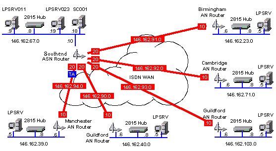
Study the schematic below: Another Subnetting Example

The network drawing above shows the IP address map for a WAN installation carried out for a large financial institution. The customer had installed 'Windows NT' servers at a number of sites and was requiring an ISDN link, star-wired out, from each of the sites from the main office server room. The IP addressing scheme had to take into account the following factors:-
- Up to 30 more sites may be added to the WAN in the near future.
- Each site could have up to 50 host connections.
- The customer had already assigned IP addresses to some of the servers and site PC's on the local LAN's.
The IP address given to this company was 146.162.0.0 (which is a Class B address), and the decision was made to use the whole of octet 3 for the subnet addresses leaving octet 4 for the host addresses. This made assigning IP addresses more easy to carry out and gave a maximum of 254 hosts per subnet and there could be a maximum of 254 subnets, thus satisfying the customer's requirements. The subnet mask for each subnet (Whether LAN or WAN) was consequently 255.255.255.0, it is important to design the addressing scheme such that the subnet mask is common to all LAN's/WAN's throughout the network unless a routing protocol such as OSPF is to be used. OSPF allows variable subnet masking.
Whilst studying the schematic you will note that the WAN links are 146.162.90.0 to 146.162.94.0 and the router ISDN interfaces are .20 at the main office end and .10 at the remote office end. Also you will note that the server IP addresses are all .5 and the ethernet hubs are all .8 while the router ethernet interfaces are all .6. Organising addressing like this can make life much easier especially when you are hopping from site to site.
RFC 950 and RFC 1812 describes IP subnetting whereas RFC 1009 defines Variable Length Subnet Masking.
Quick tricks to find subnets and broadcast addresses If you have a subnet mask, then it is possible to quickly list out the possible subnets and broadcast addresses.
The number by which subnets increment for a given mask is calculated by subtracting the last numbered octet in decimal from 256. For example, given the subnet 10.1.0.0 255.255.248.0, the last numbered octet is 248, therefore 256 - 248 = 8, so subnets jump up in 8's i.e. 10.1.8.0, 10.1.16.0, 10.1.24.0 etc.
Once you have found out by how much subnets jump, finding a broadcast address for each subnet is quickly done by subtracting 1 from this and adding this to each subnet. Using the above example, for subnet 10.1.8.0, the subnets jump in 8's, 8 - 1 = 7 and 8 + 7 = 15 so, taking it as given that the final octet will be all one's for the broadcast, the broadcast address is 10.1.15.255.


 LibreOffice
 Firefox
No comments:
Post a Comment